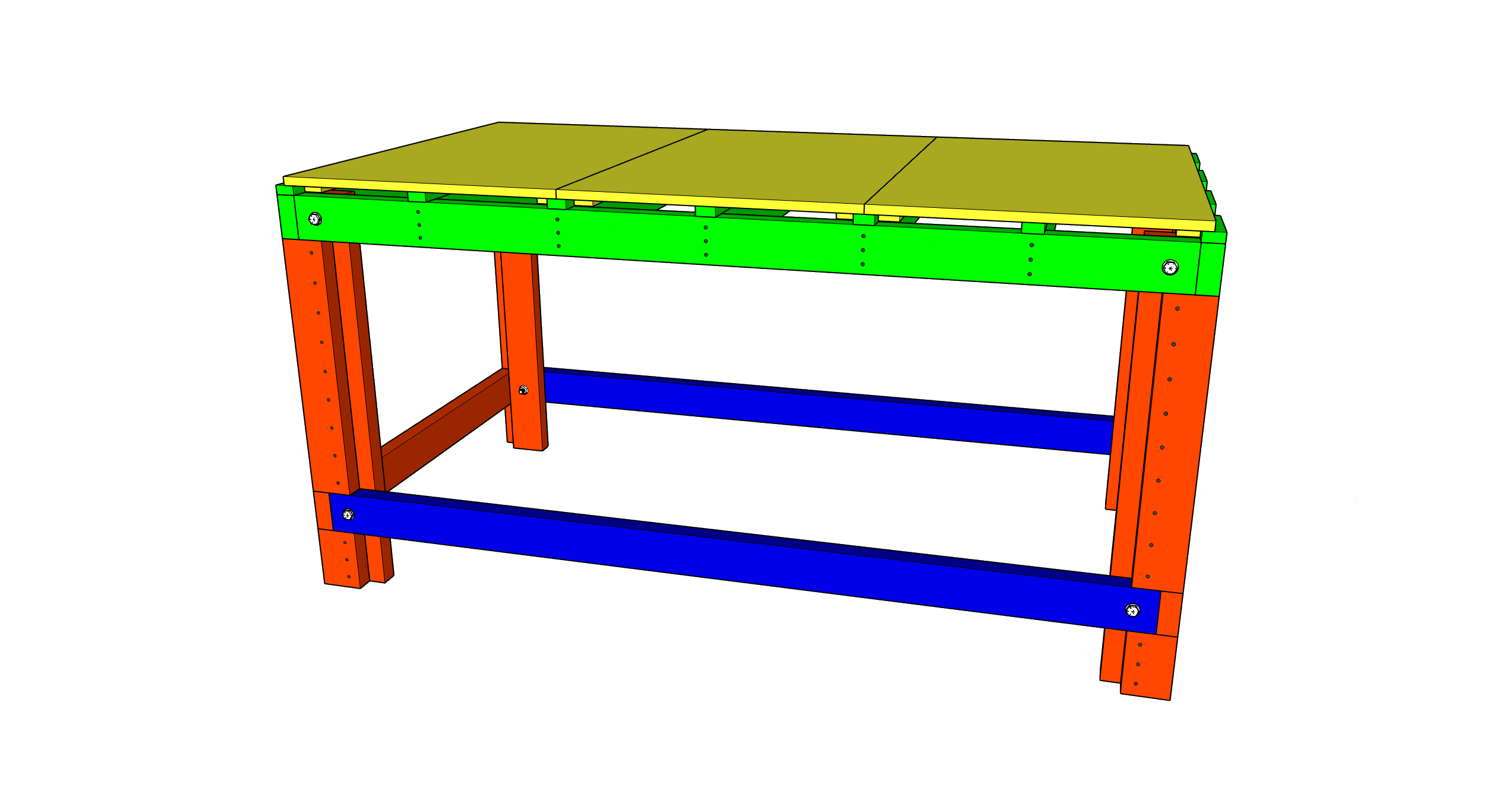
THE BUILD
STEP 1)
Cut all boards to length ** execpt ** for the TOP-SPANNERS. Those will need to be cut
to
length last. Refer to the Cut List.
Use masking tape and a marker or just use a pencil and write directly on each.
Label the boards as you cut each to ensure they don't get mixed up.
Only cut the TOP-SPANNERS
when you are ready to add them as they may end up slightly longer than 34 1/2" due to variances in
lumber.
BUILD THE LEG UNITS
STEP 2)
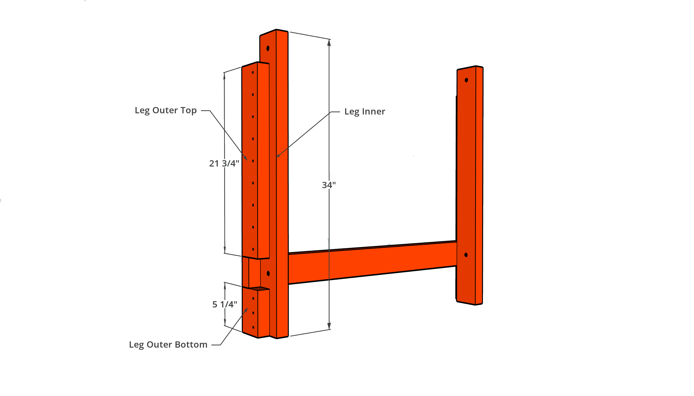
Mark & Pre Drill the 3/16" (5mm) pilot holes in the (4) - LEG-OUTER-BOTTOMS
Don't worry about orientation at this point
Make sure your holes are 1" inch from the edge

STEP 3)
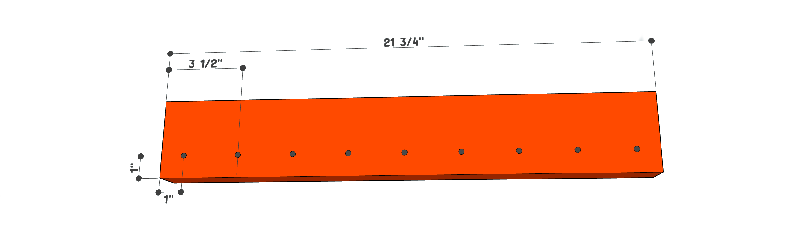
Mark & Pre Drill the 3/16" (5mm) pilot holes in the (4) - LEG-OUTER-TOPS
Spacing between the pilot holes is not critical.
Make sure your holes are 1" inch from the edge
STEP 4)
Mark & Pre Drill the 3/16" (5mm) pilot holes in the (2) - LEG-SPANNERS
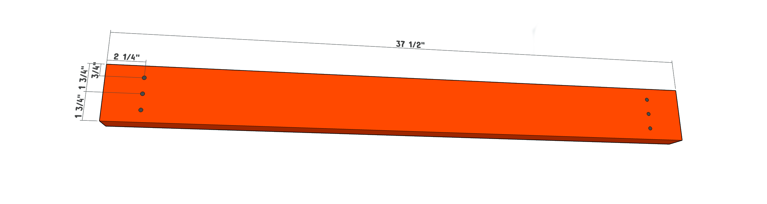
CRITICAL NOTE:
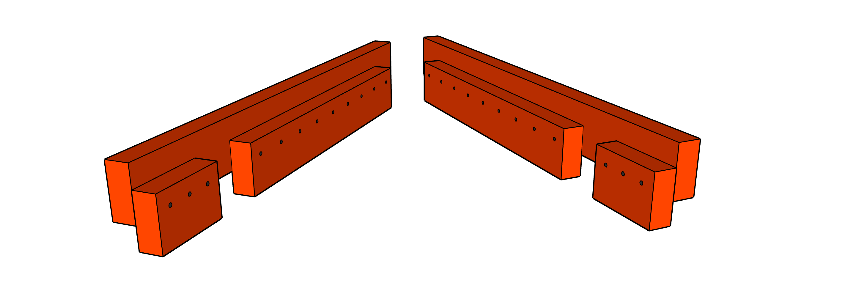
There are (2) - RIGHT SECTIONS and (2) - LEFT SECTIONS for the next (2) STEPS
They are mirror opposites
STEP 5)
Attach the (4) - LEG-OUTER-BOTTOMS to the (4) - LEG-INNERSYou can use glue which will produce a stronger bond (and WORK TABLE),
but if a part gets damaged it's not easily replaced.
You can temporarily lay your LEG-INNERS on top of the LEG-SPANNERS
and that will give you perfect spacing.
Make sure the (2) bottoms (ENDS) are flush with each other.
(Use the 2-1/2" screws)
It helps if you go ahead and put your screws into the pilot holes of the piece you are attaching
STEP 6)
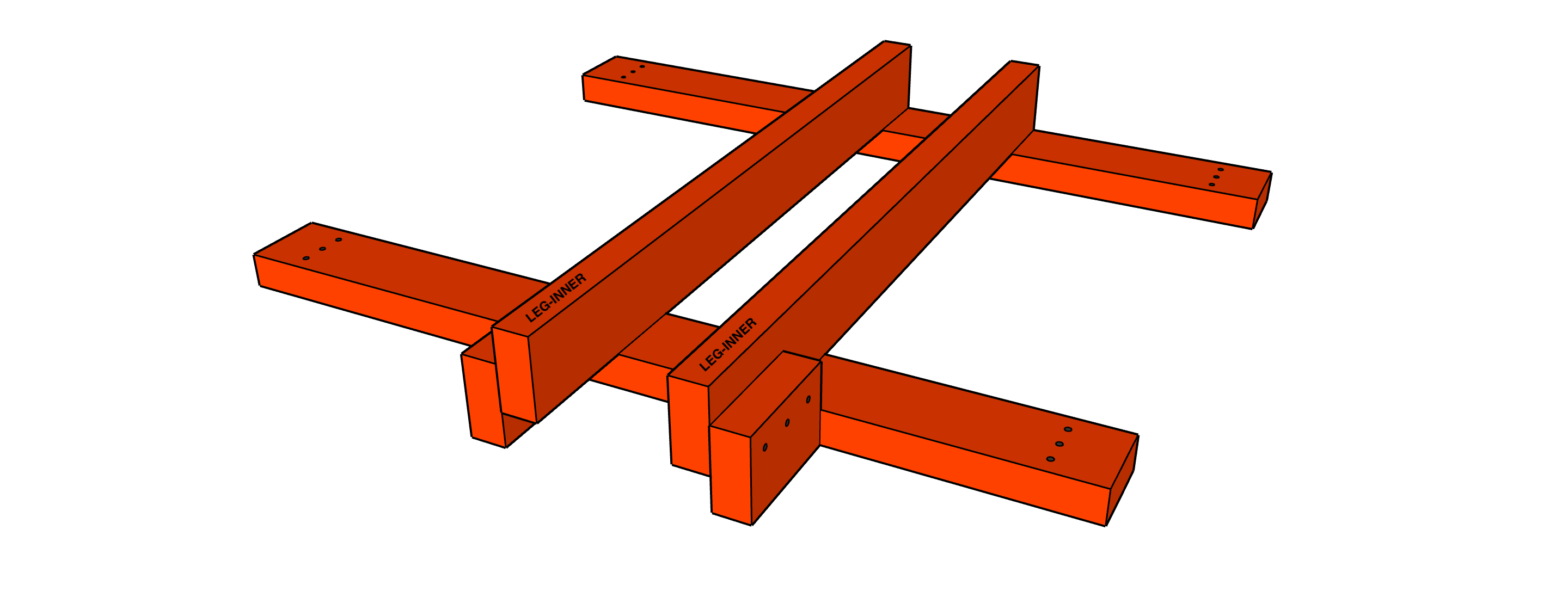
Attach the (4) - LEG-OUTER-TOPS to the (4) - LEG-INNERS using the same techique as above.
The 2x4 should
be a spacer to
separate the LEG-OUTER-TOPS and the LEG-OUTER-BOTTOMS.
(Use the 2-1/2" screws)
STEP 7)
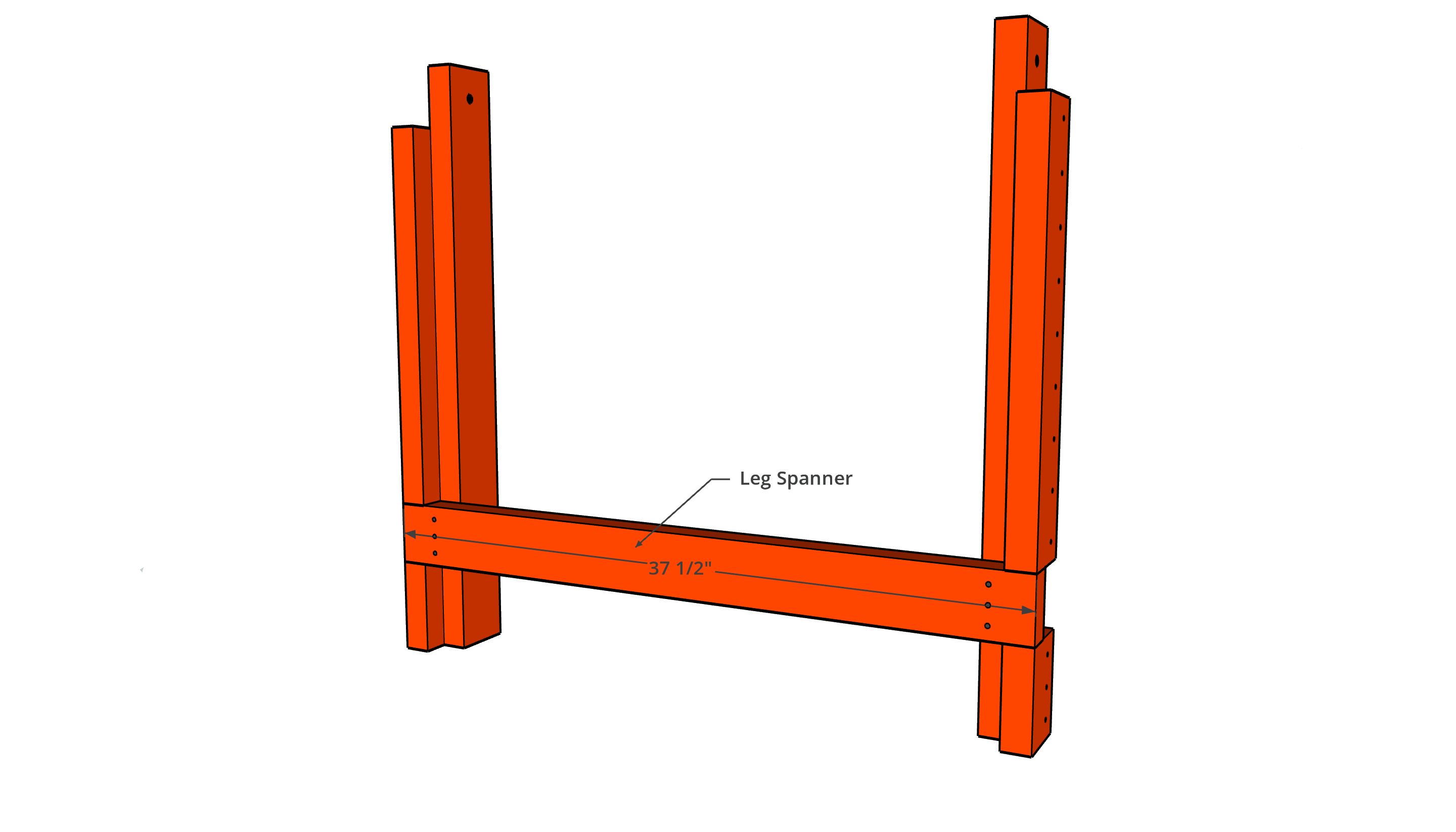
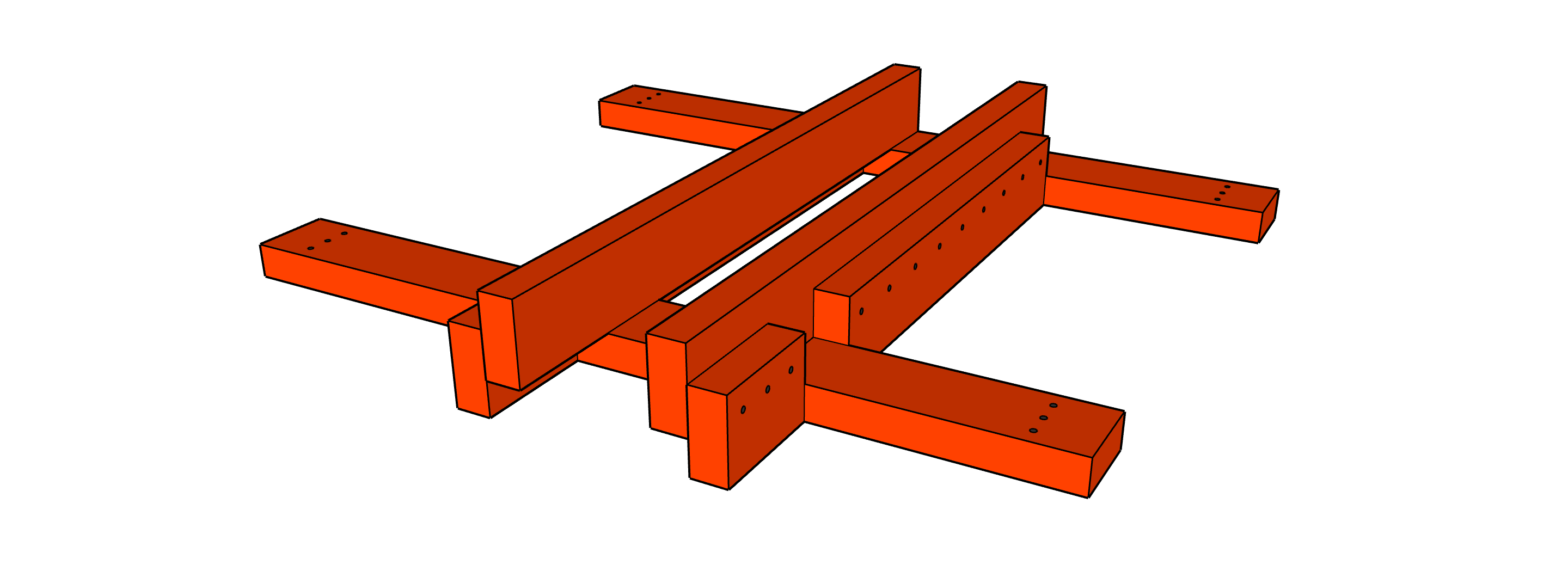
Attach the (2) - LEG-SPANNERS to the (4) - LEG-INNERS
Make sure your edges are flush
(Use the 2-1/2" screws)
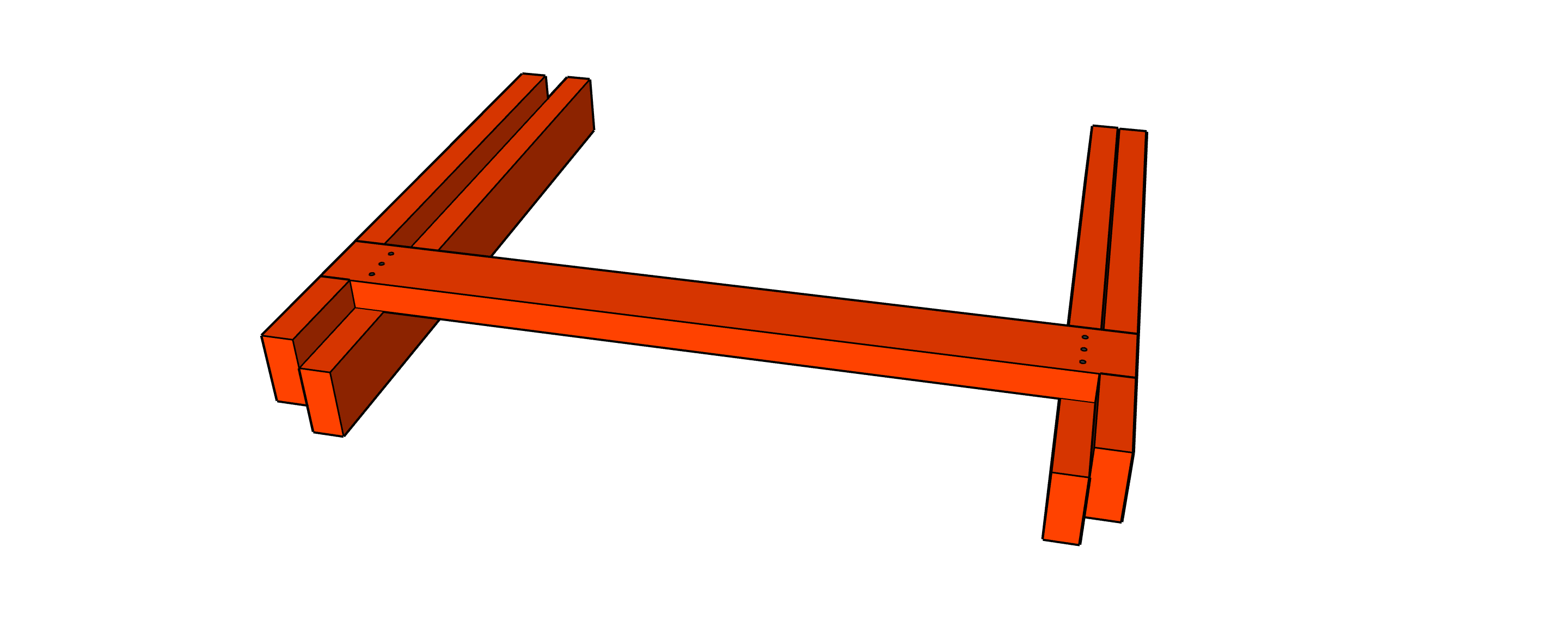
You should have (2) completed (free standing) LEG-UNITS at this point
STEP 8)
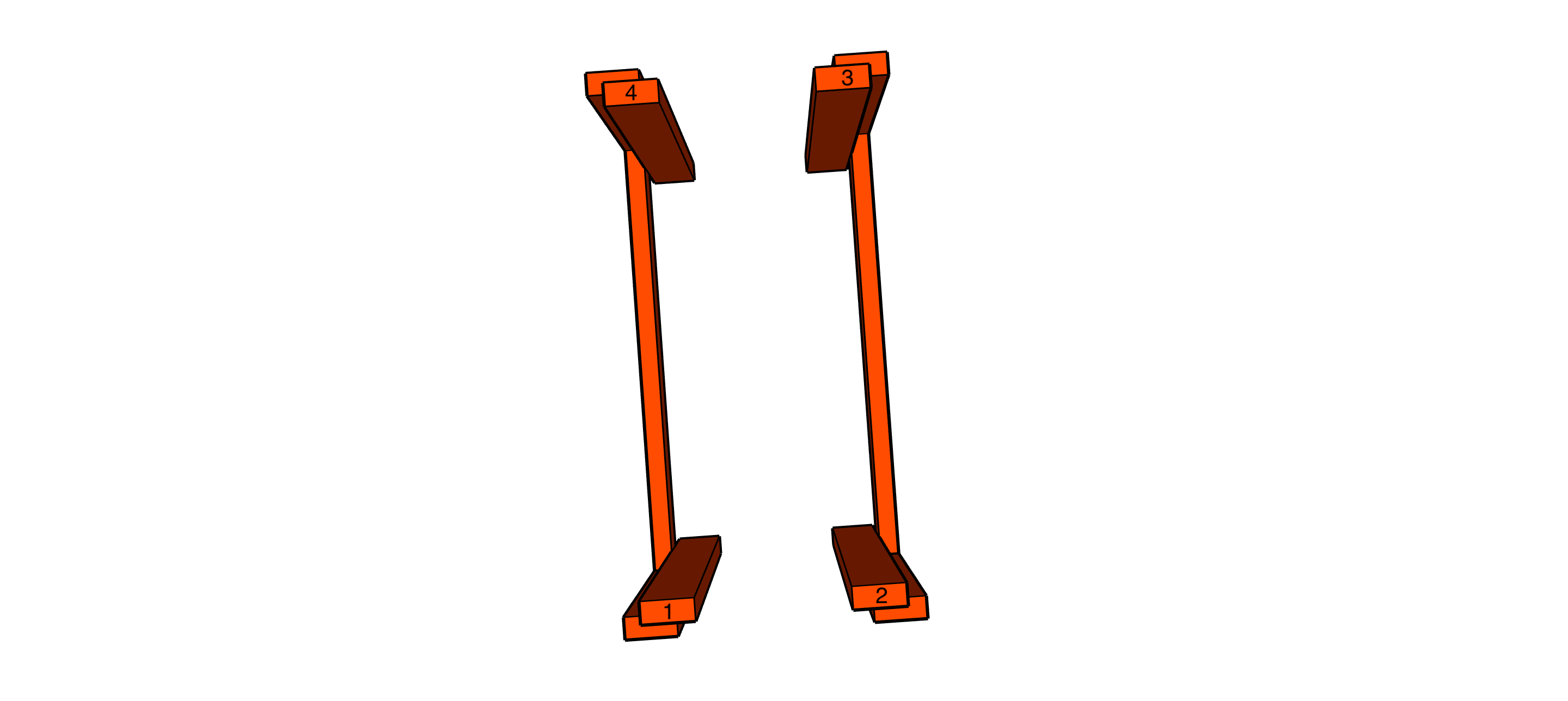
** Number the corners **
The tops of the (4) LEG-INNERS on the (2) - LEG-UNITS
should be NUMBERED with a MARKER to insure good fit everytime you assemble the table.
I like to go counter-clockwise.
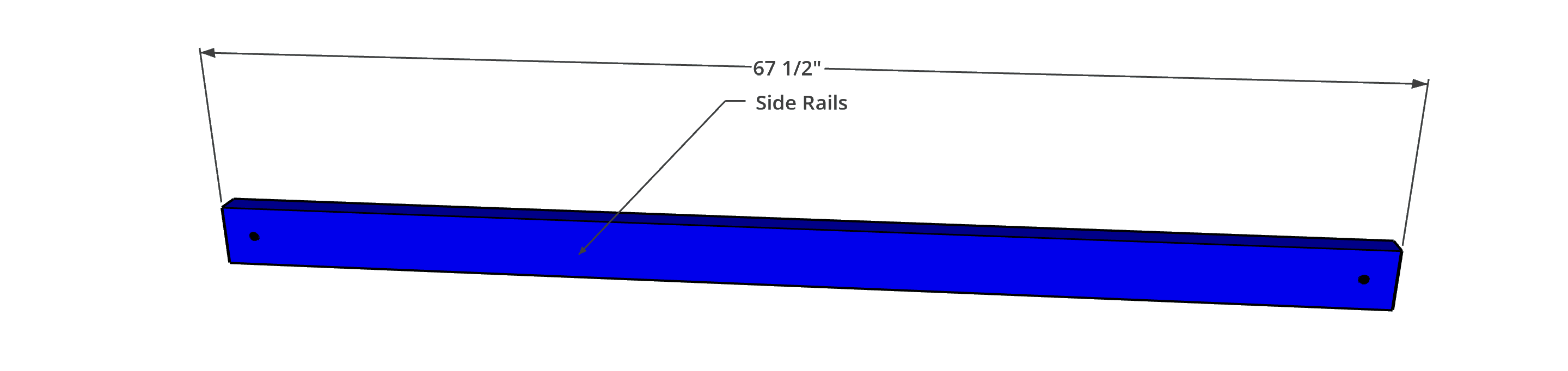
THE SIDE RAILS
STEP 9)
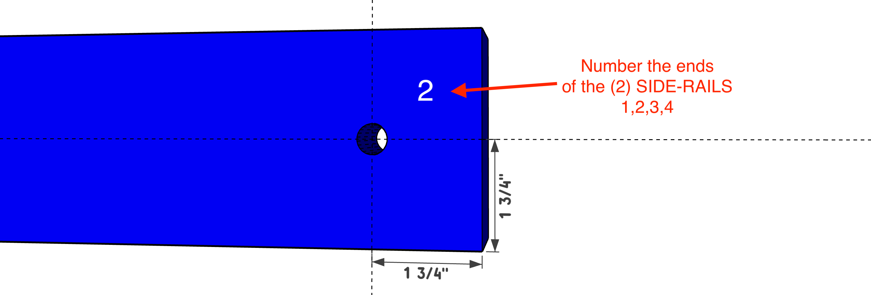
Mark & Drill out the 1/2" (13mm) holes for BOLTS in the (2) SIDE-RAILS. Number the (4) ends of the SIDE-RAILS, beside the 1/2" BOLT holes, to match the numbers on the (4) LEG-INNERS on the (2) LEG UNITS. These numbers will corespond to the LEG-UNITS when drilling out the holes. The ends of the SIDE-RAILS and the corners of the TOP-UNIT should be numbered to match.
STEP 10)
At this point you can Drill out the 1/2" (13mm) holes for the BOLTS into the LEG UNITS using the
SIDE-RAILS 1/2" holes
you've already drilled out as a guide. The LEG-UNITS should be free standing and make drilling out
and
attachment easier. Use the BOLTS, NUTS and WASHERS and attach them to the LEG-UNITS as you complete
each.
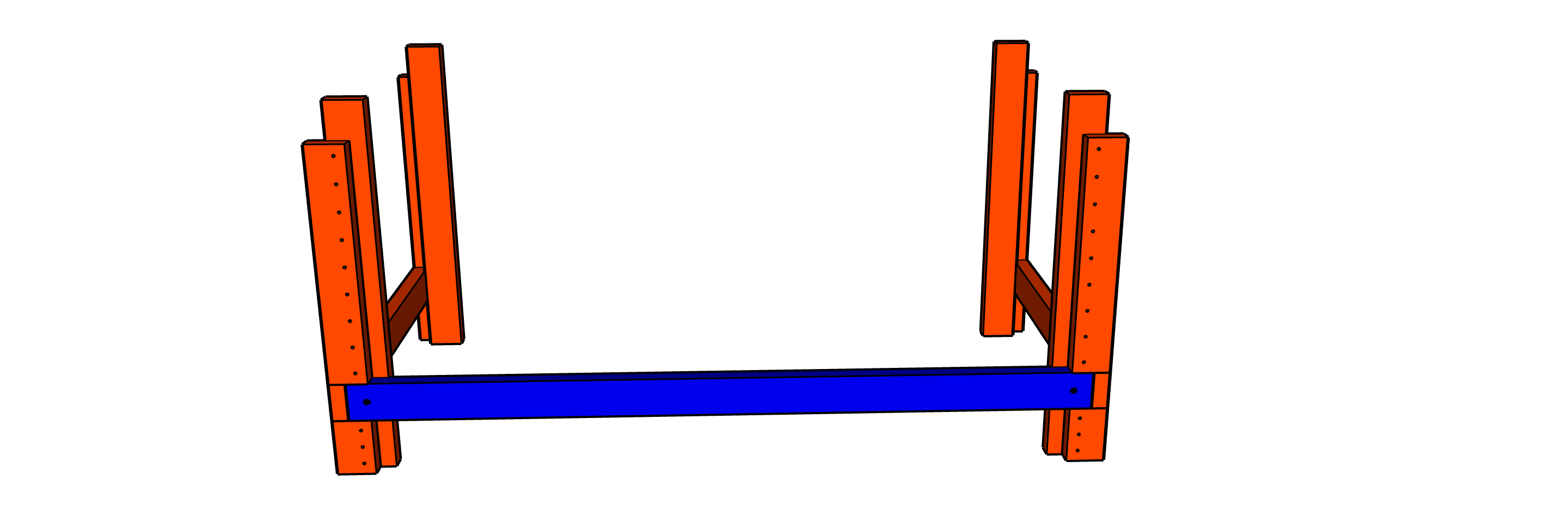
STEP 11)
Then drill out and attach the other SIDE-RAIL on the other side with BOLTS, NUTS and WASHERS.
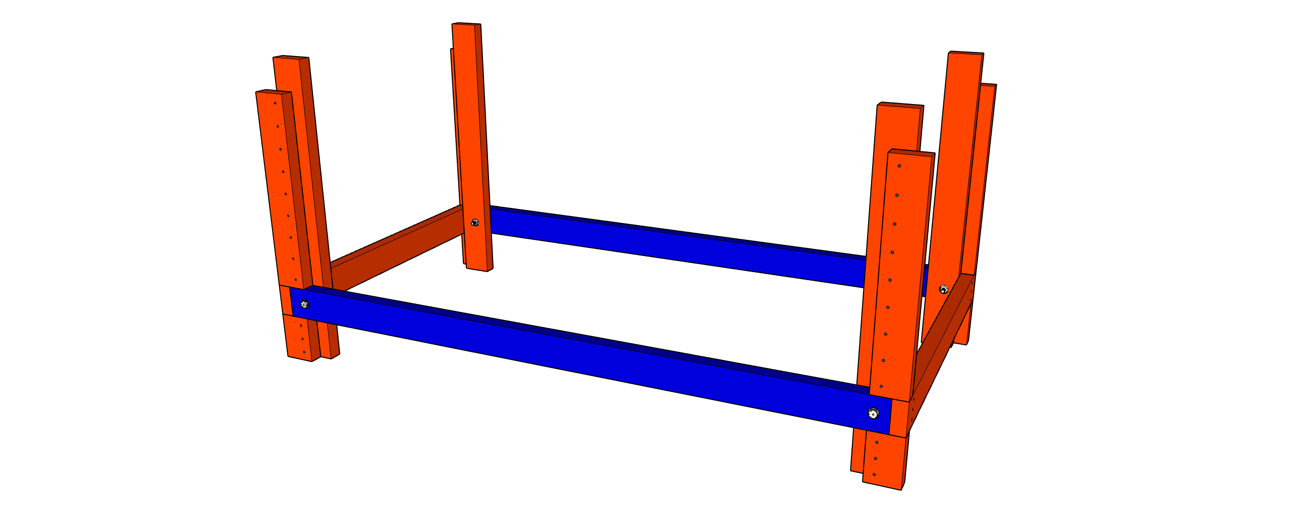
NUMBER the ends of the SIDE-RAILS to match the top numbers on the leg units
BUILD THE TOP UNIT
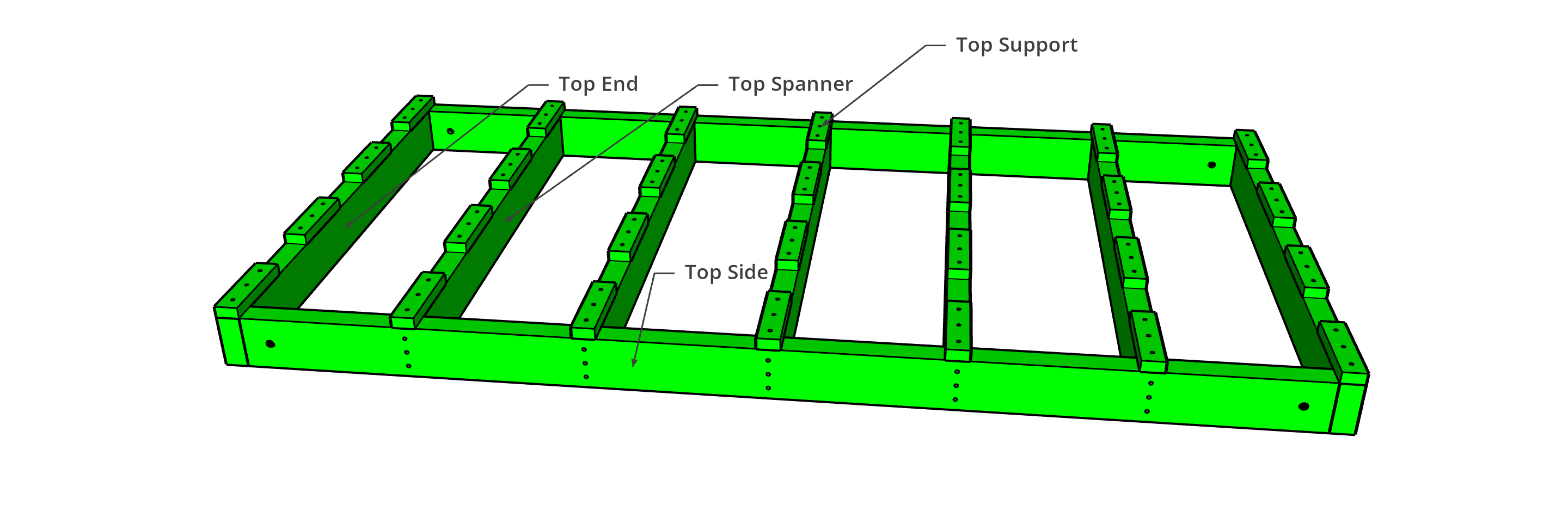
STEP 12)
Mark & Drill out 1/2" (13mm) holes for Bolts in the (2) - TOP SIDES

STEP 13)
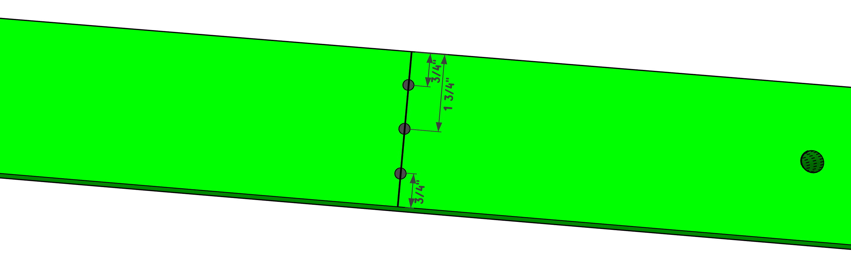
Measure out and mark a line on the TOP and on One Side of each of the (2) TOP-SIDES at each of the given measurements. You can do both TOP-SIDES at the same time. These are guide lines to line up the (5) TOP-SUPPORTS and for drilling the 3/16" (5mm) pilot holes in the (2) TOP-SIDES.
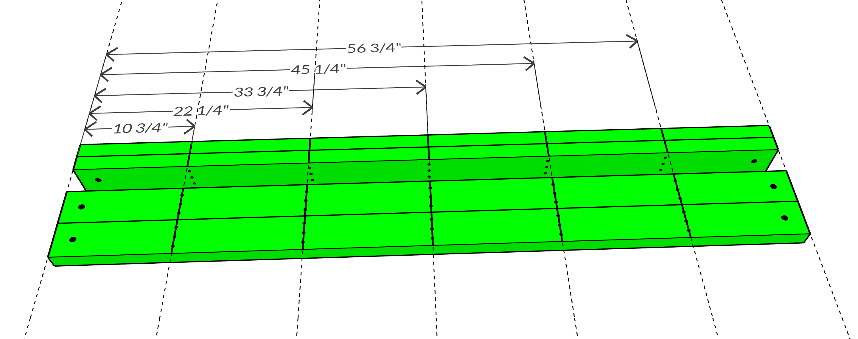
STEP 14)
Mark & Pre Drill the 3/16" (5mm) pilot holes in the (2) - TOP SIDES
There should be (5) sets of (3) pilot holes. These are for attaching the TOP-SPANNERS
STEP 15)
Mark & Pre Drill the 3/16" (5mm) pilot holes in the (2) - TOP ENDS

STEP 16)
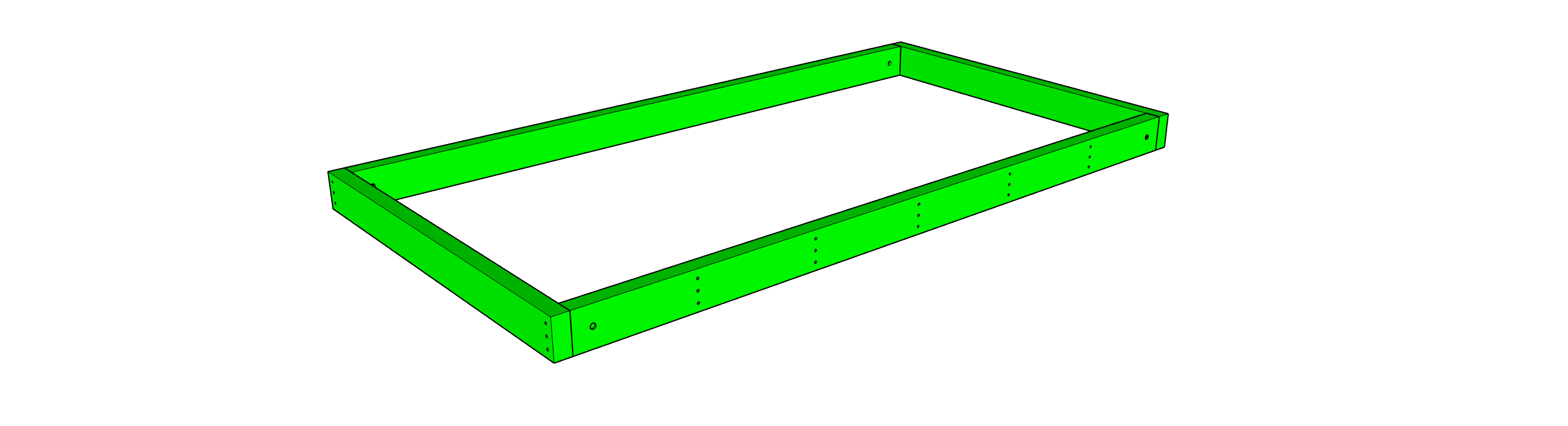
Attach TOP-ENDS to TOP-SIDES
(Use the 2-1/2" screws)
STEP 17)
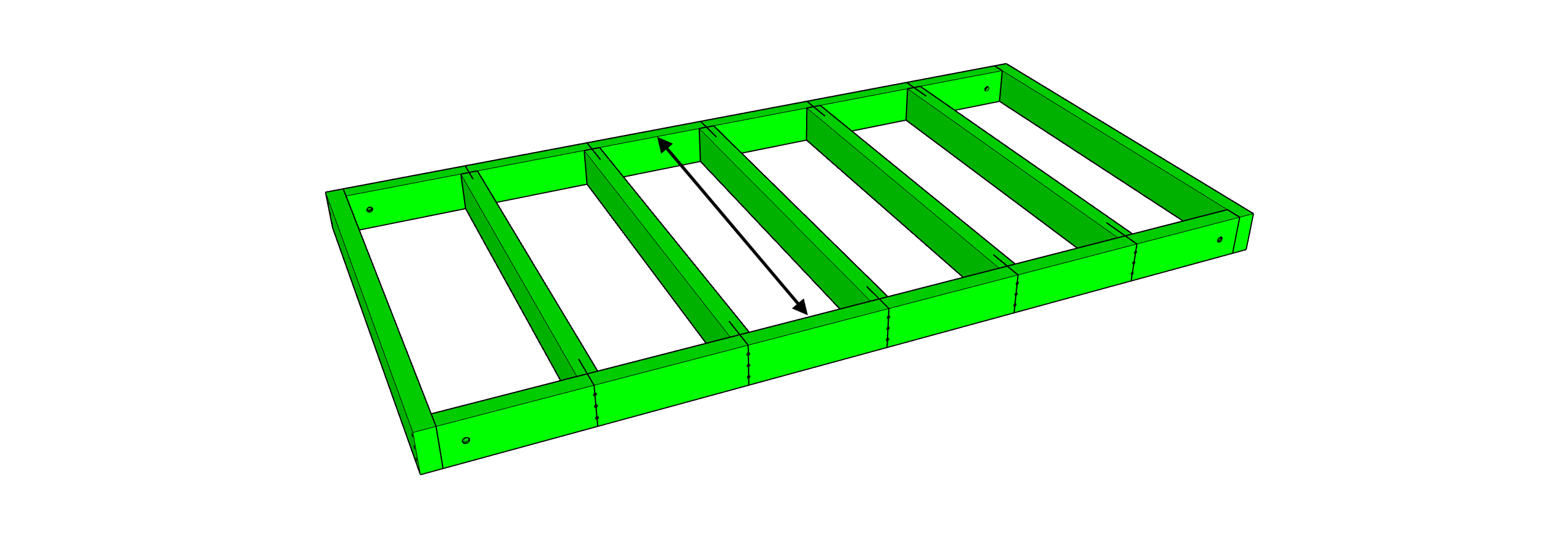
To get a good fit you'll need to measure from the insides of the (2) TOP-SIDES
Now you can Cut your (5) TOP-SPANNERS.
Find the Center of the TOP-SPANNERS and align with marks you made in STEP 13
Attach (5) TOP-SPANNERS to the (2) TOP-SIDES
(Use the 2-1/2" screws)
STEP 18)
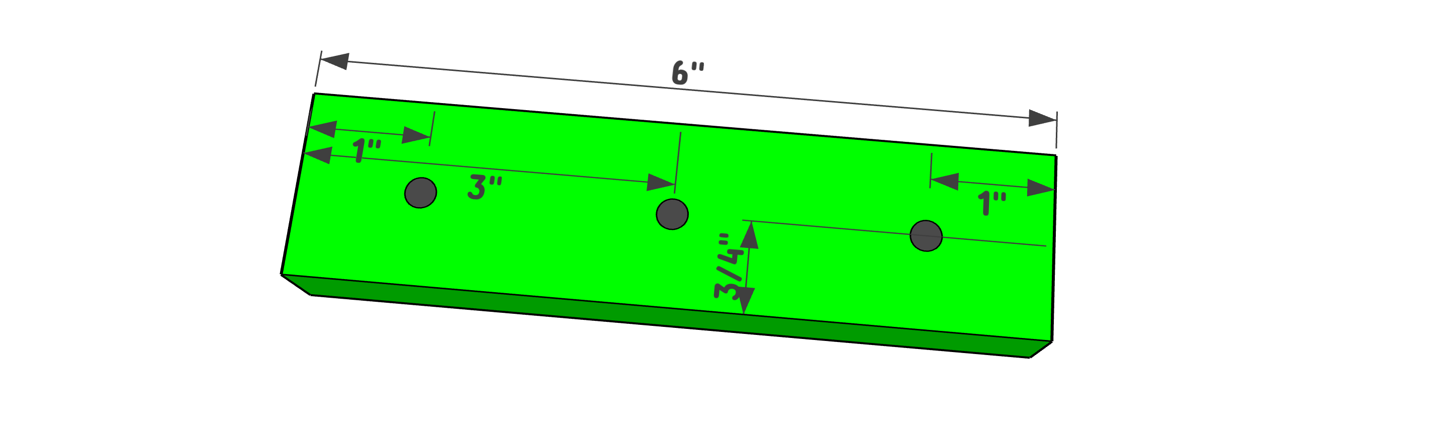
Cut the (28) TOP_SUPPORTS from the 1x2 boards.
Mark & Pre Drill the 3/16" (5mm) pilot holes in each
STEP 19)
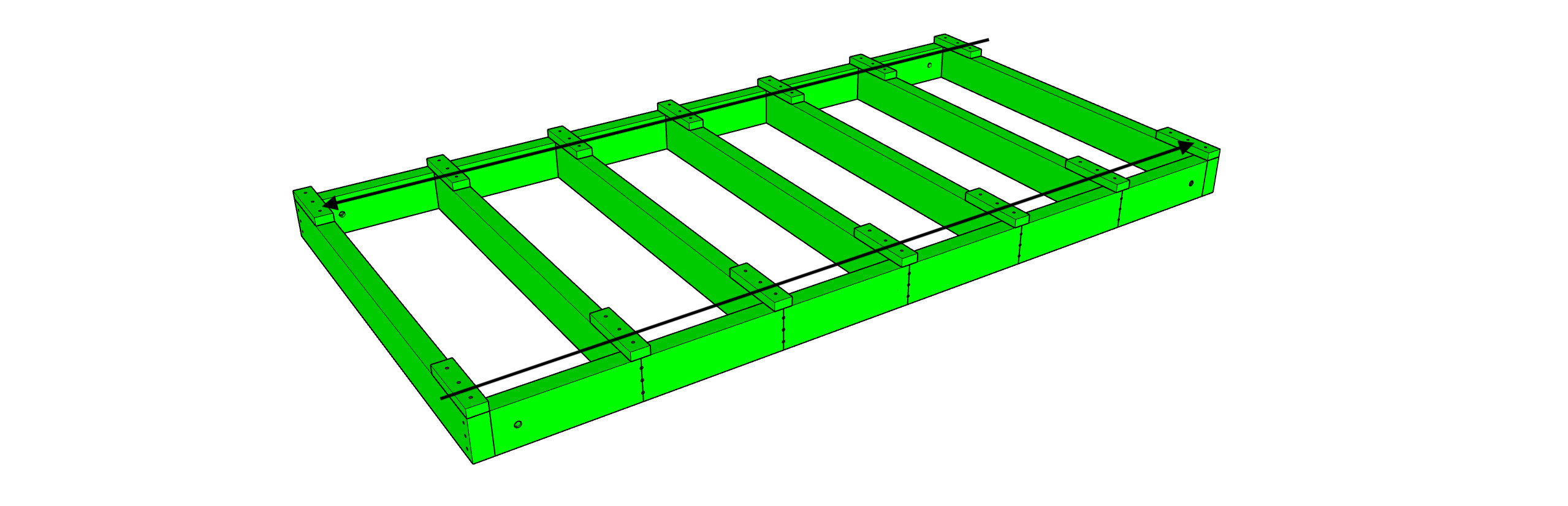
Attach the 2 outer rows of TOP-SUPPORTS
Make the outer edges flush with the TOP-SIDES
(Use the 1-1/4" screws)
STEP 20)
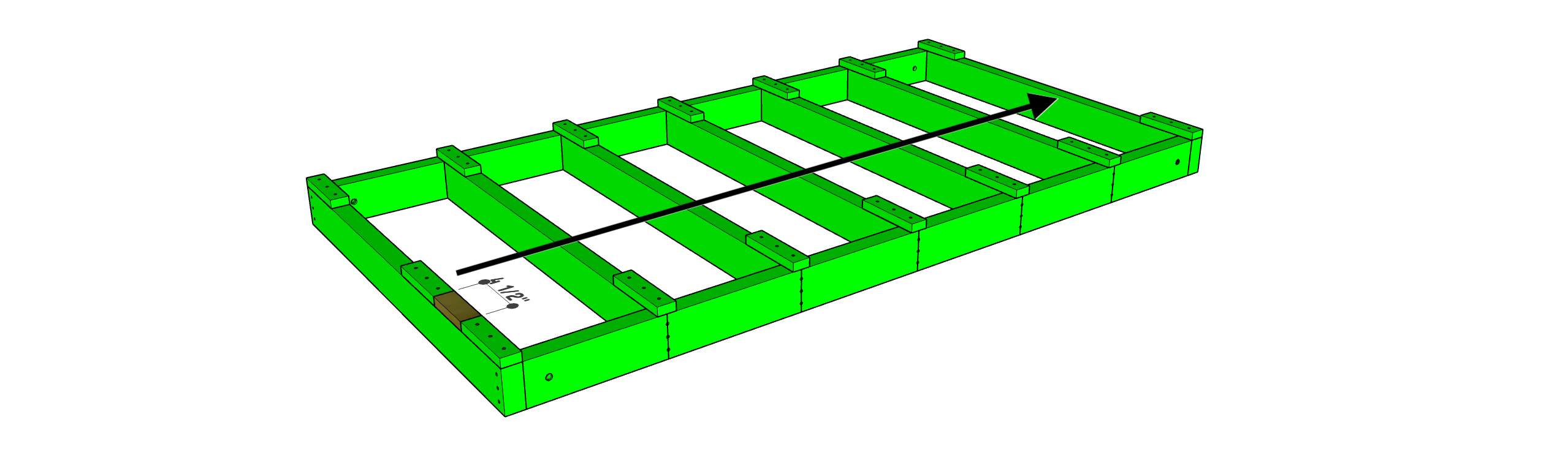
Cut a 4-1/2" spacer from the 1x2 boards.
Use this to evenly space the first inner row of
TOP-SUPPORTS
(Use the 1-1/4" screws)
STEP 21)
Use the same 4-1/2" spacer to evenly space the second inner row of TOP-SUPPORTS
(Use the 1-1/4" screws)
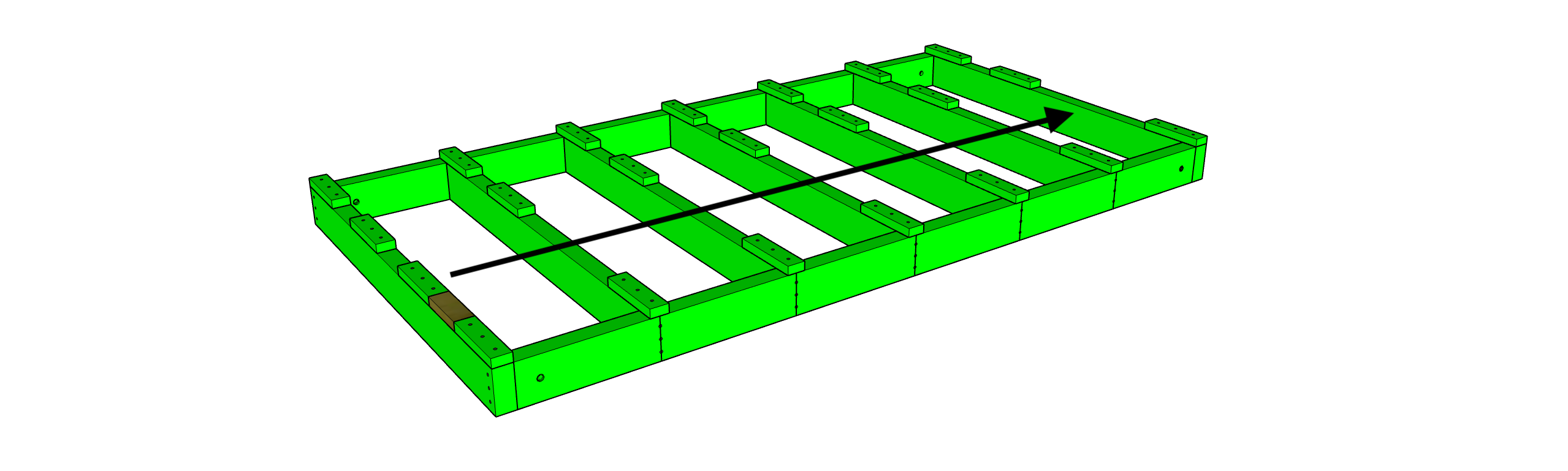
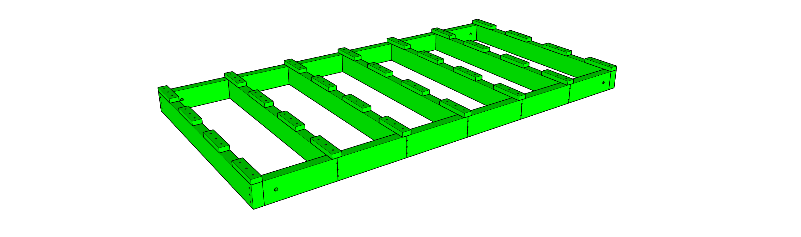
At this point the TOP-UNIT should be completed.
STEP 22)
Number the (4) coners of the TOP-UNIT
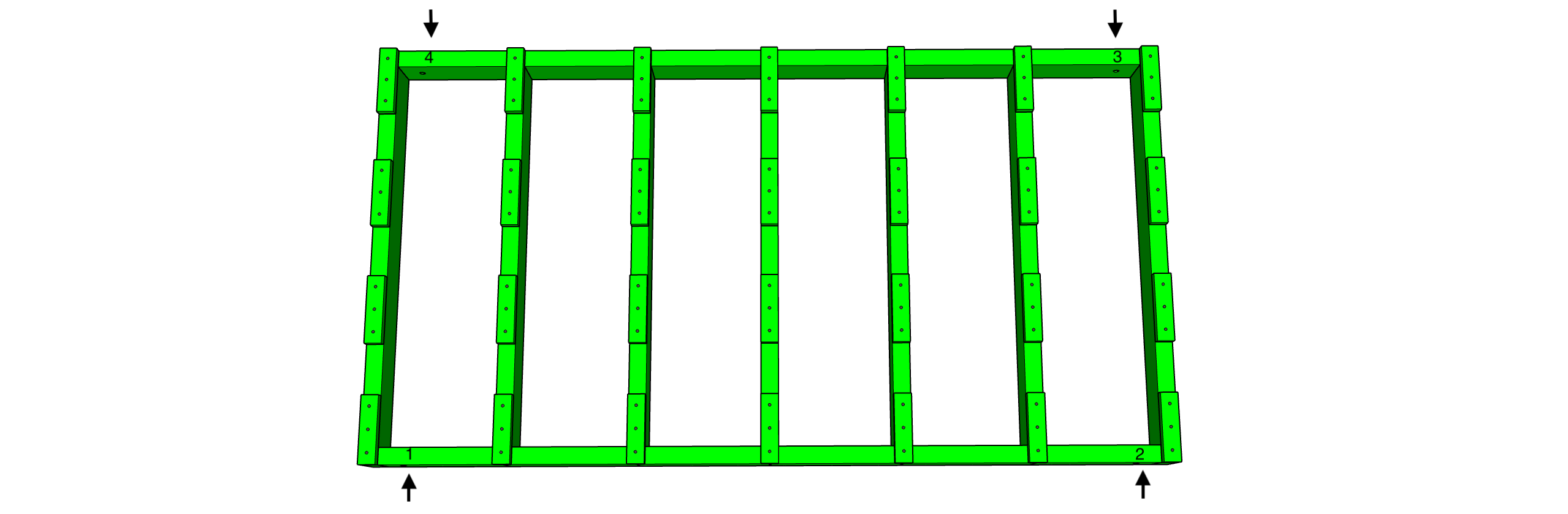
STEP 23)
Now we can add the TOP-UNIT to the (2) LEG-UNITS and the SIDE-RAILS.
Match the numbers from the tops of the LEG-UNITS to the corners of the TOP-UNIT.
Use the 1/2" holes you drilled into the TOP-SIDES as a guide to drill the bolt holes into
the LEG-INNERS. You can now use your other BOLTS, NUTS and WASHERS to attach the TOP-UNIT
Always match your numbers when assembling THE WORK TABLE
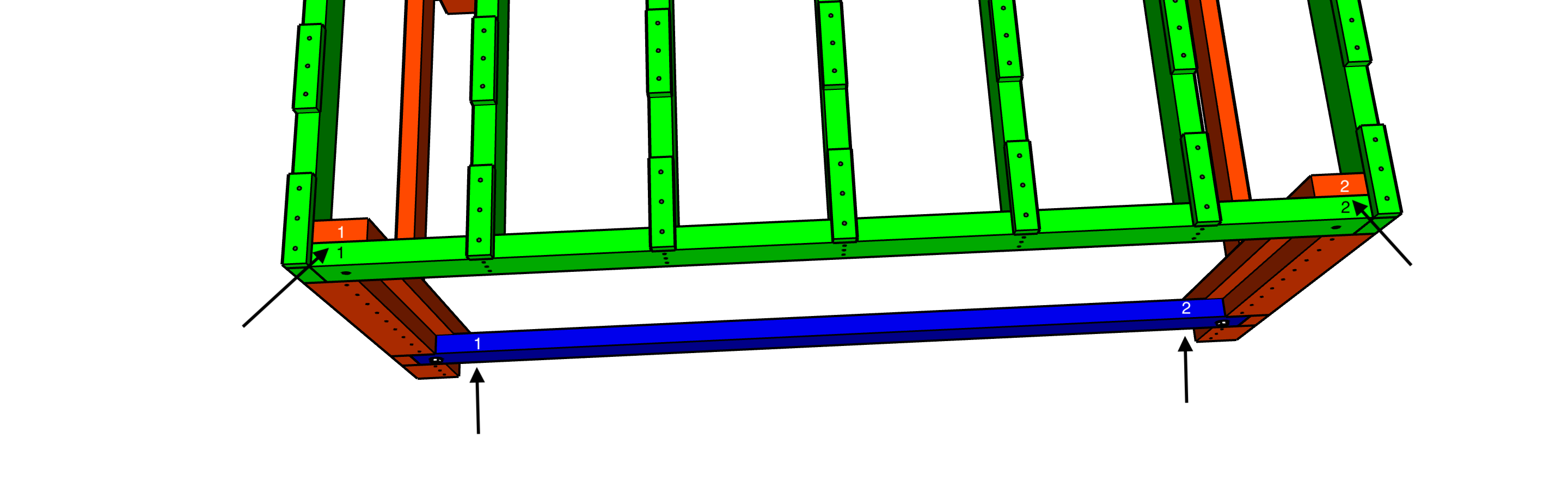
The WORK TABLE is completed
TABLETOP/SHELF
STEP 24)
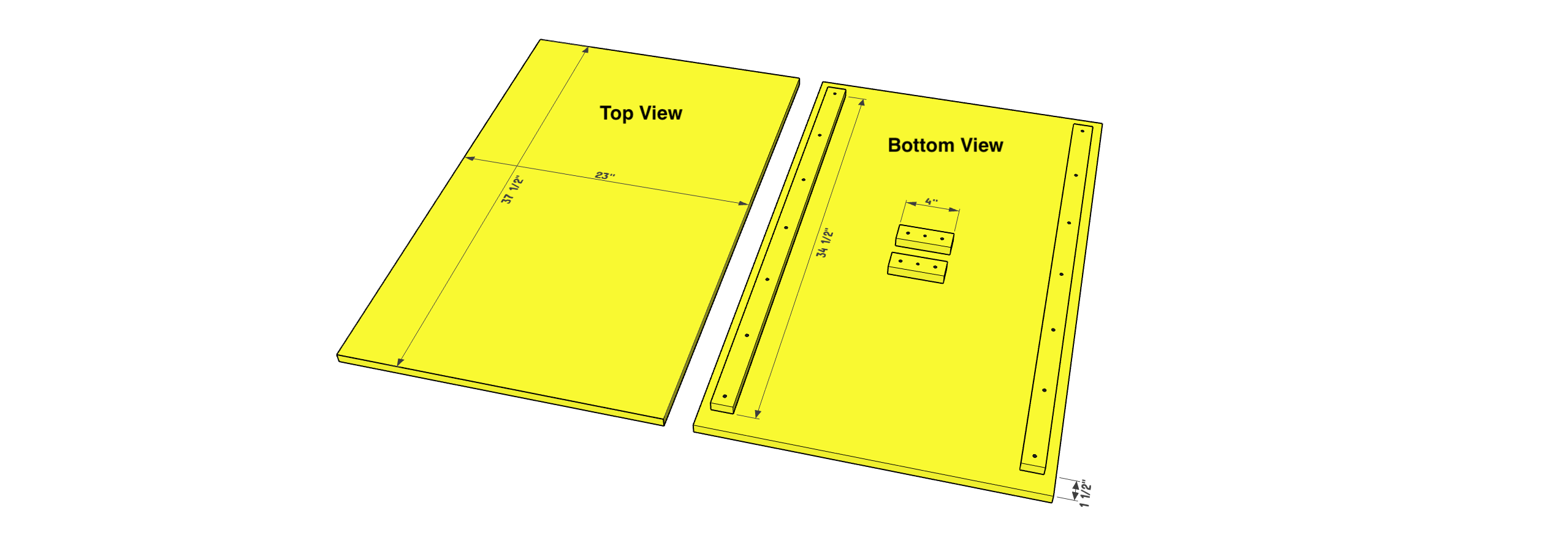
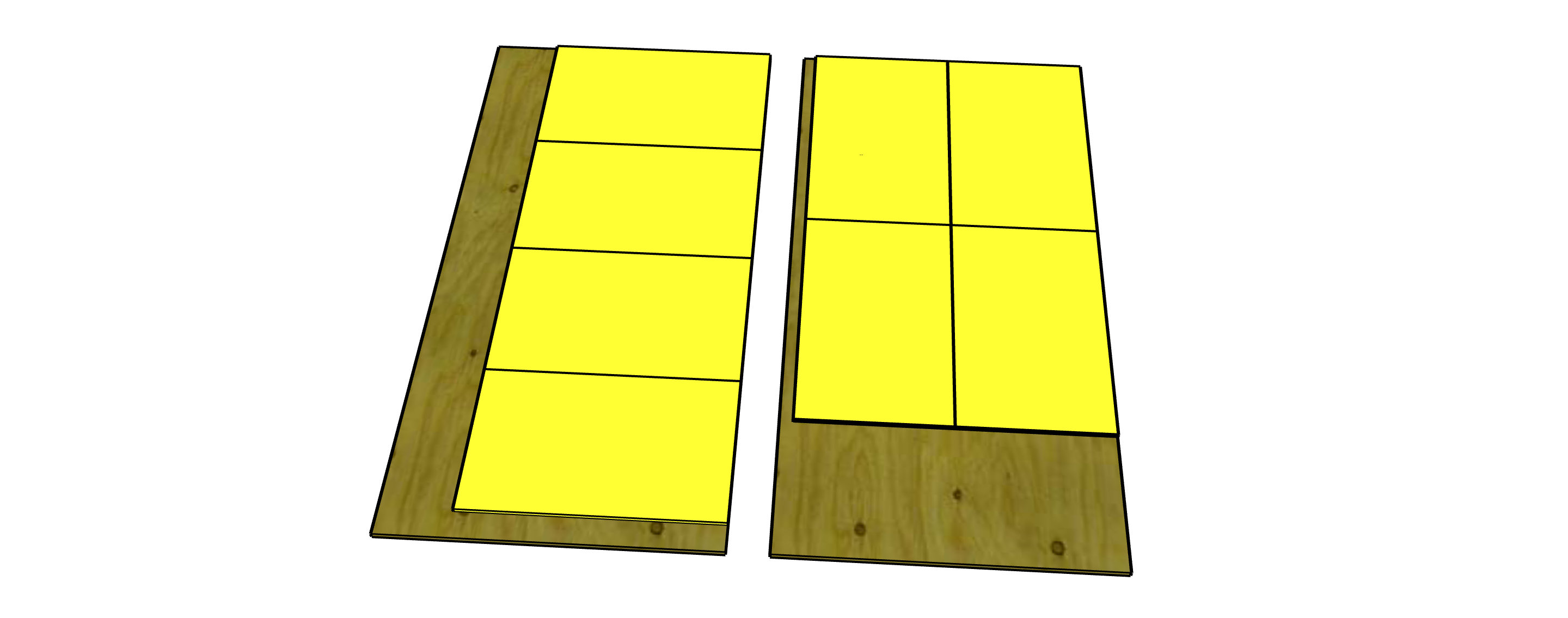
Cut your TABLE-TOPS to size.
Here are (2) possible layouts if cutting your TOPS from a 4x8 sheet of plywood.
1/2" plywood will work but 3/4" is recommended.
STEP 25)
Lay out your 3 Table-Top boards on a flat surface. Make sure they are touching and flush with each other on the ends.
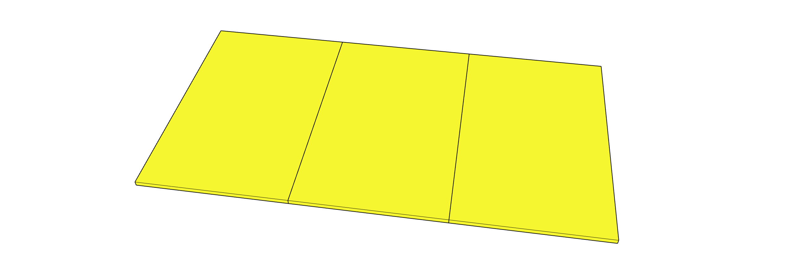
STEP 26)
Lay the TOP-UNIT upside down on top of the TABLE-TOP boards. Make sure all the edges fall in the middle of a TOP-SUPPORT. The (2) short side edges should be about 3/4" from the the edge. The long side edges should be flush.
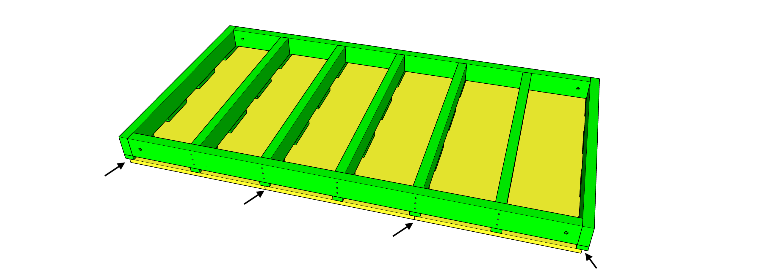
STEP 27)
Be careful that nothing moves. Install one of the 4" pieces against the TOP-SUPPORT in the middle. (Use (2) of the 1-1/4" screws) on either side. You can install the middle screw later.
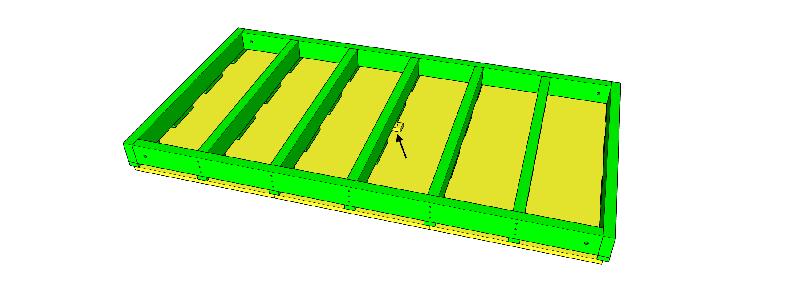
STEP 28)
Next install another of the 4" pieces tightly against the oposite TOP-SUPPORT in the middle. (Use (2) of the 1-1/4" screws) on either side. You can install the middle screw later.
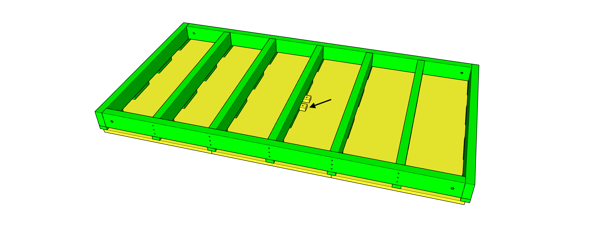
STEP 29)
Next install one of the 34-1/2" pieces against the side of the TOP-SUPPORTS. The ends should be flush with the insides of the TOP-SIDES (Red Arrow). Be careful nothing moves.
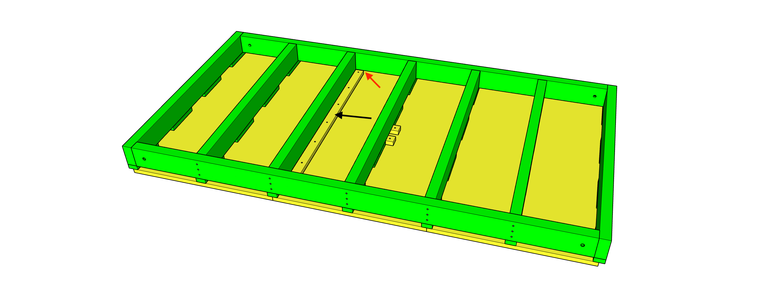
STEP 30)
Next install another one of the 34-1/2" pieces against the side of the TOP-SUPPORTS on the other side. Again the ends should be flush with the insides of the TOP-SIDES (Red Arrow).
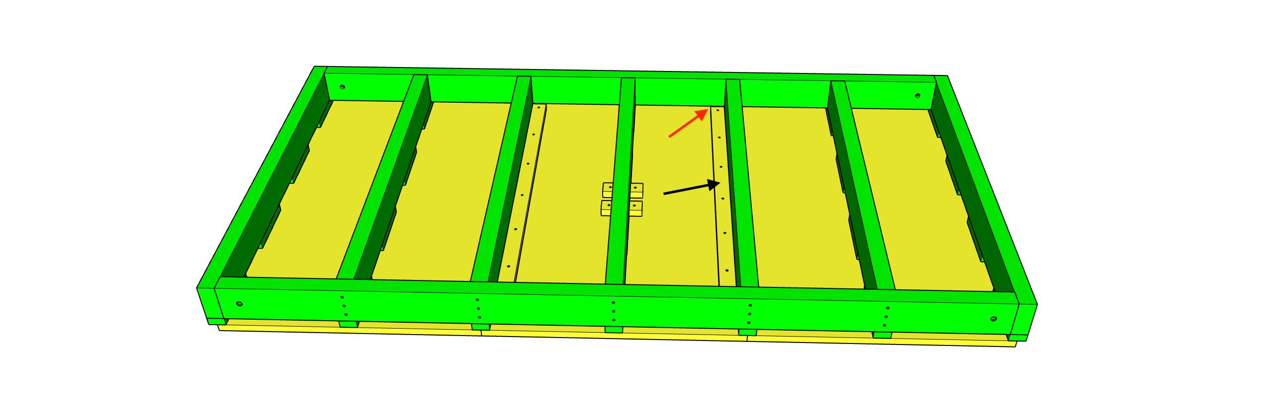
STEP 31)
Using STEPS 27-30 as a guide, install 1x2 pieces onto the other (2) TABLE-TOPS.
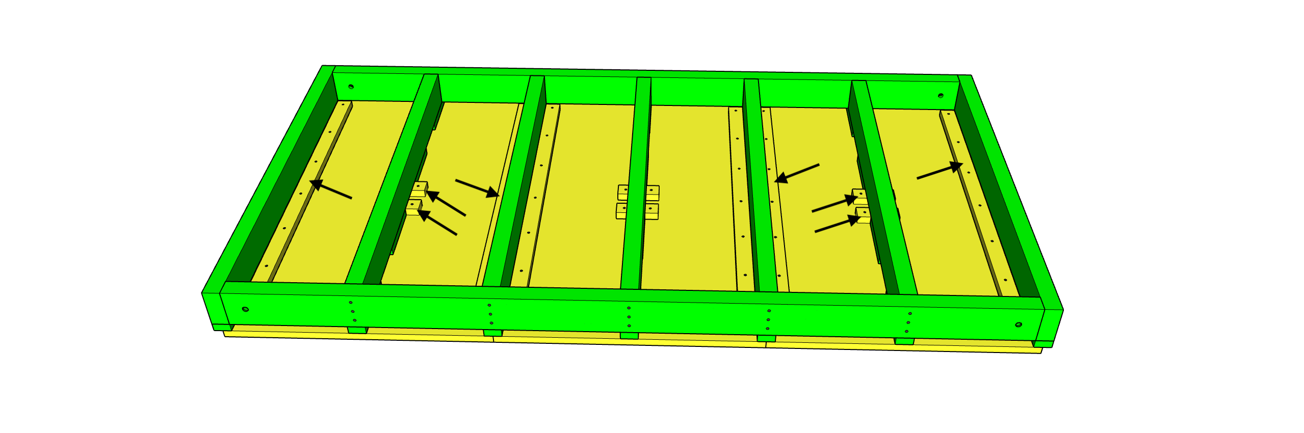
STEP 32)
Number the corners of your TABLE-TOPS to match the corners of your WORK TABLE so everything aligns everytime its assembled.
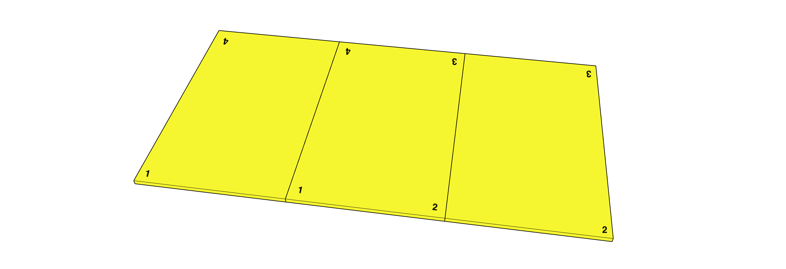
Completed